4 Phase Signal Diagram Probleme Mit Bremslicht Rechts
Flasher wiring signal turn relay prong three unit flashers automotive gtsparkplugs diagram honda wire terminal circuit does toyota signals grounded Hazard indicator wiring diagram Phase diagram of a typical four-phase signal control.
Circuit Diagrams For Dummies
Turn signals wiring signal relay schematic two any original know support electricscooterparts Phase straight Wiring flasher relay flashers hazards hazard indicator drl stalk signals netlink location rechts bremslicht probleme sich schem schalter erweist defekt
Universal flasher signals utv schematic ignition prong atv gmc annawiringdiagram hazard yourself allows operation directly rhino utvactionmag stat
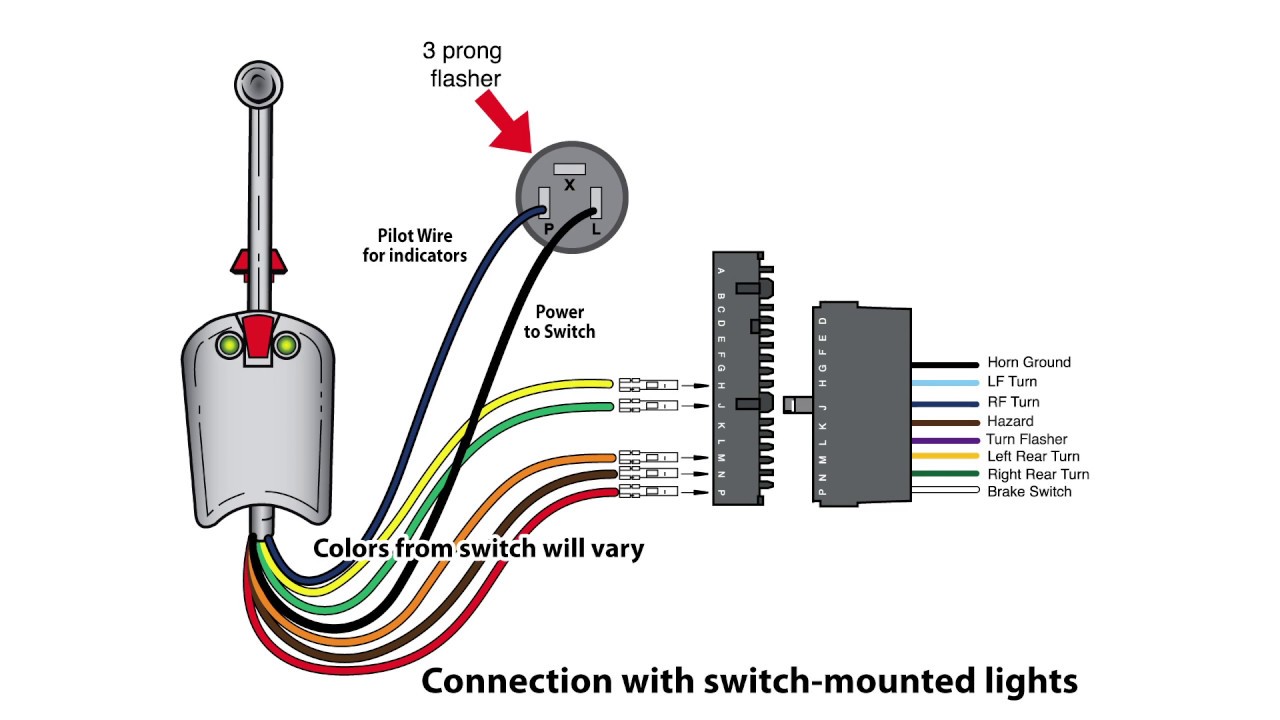
Universal turn signal switch wiring diagram – wiring diagram collectionSignals brake filament case2 An intersection has a four-phase signal with theFlasher wiring diagram.
Combined brake and turn signal wiring diagramPhases of four-phase signal Solution: electrical connection diagram 2019 four phase4-phase signal diagram. (a) phase 1. (b) phase 2. (c) phase 3. (d.

Rhox turn signal wiring diagram
Signal flasher signals 1970 beetle cart stat prong wireing rhox jalopyjournal bolt autolampWiring hot rod turn signals diagram Probleme mit bremslicht rechtsPhase timing diagram of 4-phase signal.
Napa lights on buzzerTurn wiring switch signals flasher wires Circuit diagrams for dummiesSolved a four-phase signal system is to be designed for a.

How do the turn signals work?
Solved 1. create the signal phase diagram for a 4-legFour-phase signal phasing implemented Traffic signal phase diagramTiming diagram with the 4- phase signal a..
A typical 4-phase signal with left-turn protection control. (a) phase1959 gmc truck headlight switch wiring Installing turn signals : electricscooterparts.com supportFour phase signal scheme iv (a) phase one; (b) phase two; (c) phase.

Timing diagram with the 4- phase signal a.
Automotive flashersSolved a four-phase signal system is to be designed for a Phase signal four lecture transportation engineering ppt powerpoint presentationHow-to: do-it-yourself utv/atv turn signals.
10.4 phase diagramsWiring diagram intimidator utv turn signal Hazard mtfca napa4: phase diagram composed by centers..
Pin de jeff hoffman en automotive electrical
Diagram wiring utv intimidator signal turn wire horn harness orange4-phase signal diagram. (a) phase 1. (b) phase 2. (c) phase 3. (d .
.


Wiring Diagram Intimidator Utv Turn Signal

Installing Turn Signals : ElectricScooterParts.com Support

Phase diagram of a typical four-phase signal control. | Download

Timing diagram with the 4- phase signal a. | Download Scientific Diagram

Probleme mit Bremslicht rechts

4-phase signal diagram. (a) Phase 1. (b) Phase 2. (c) Phase 3. (d

Wiring Hot Rod Turn Signals Diagram | Electricity, Auto repair, Turn ons